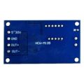
ماژول تایمر قابل تنظیم 12 تا 24 ولت با خروجی CMOS
توضیحات محصول
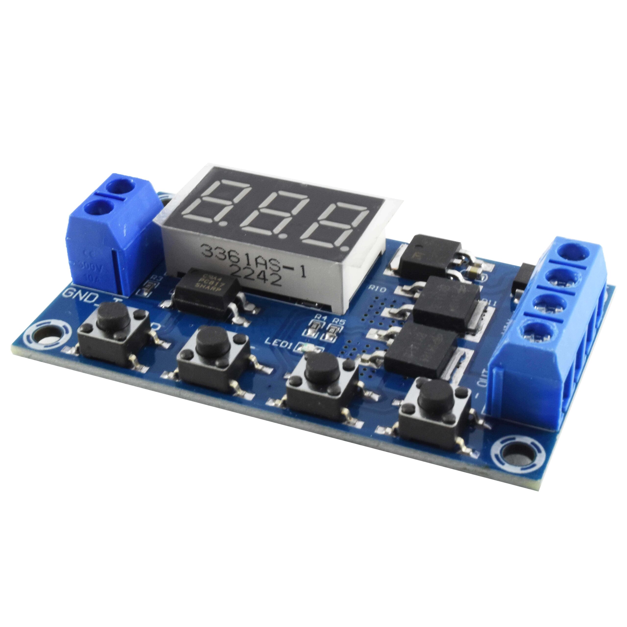
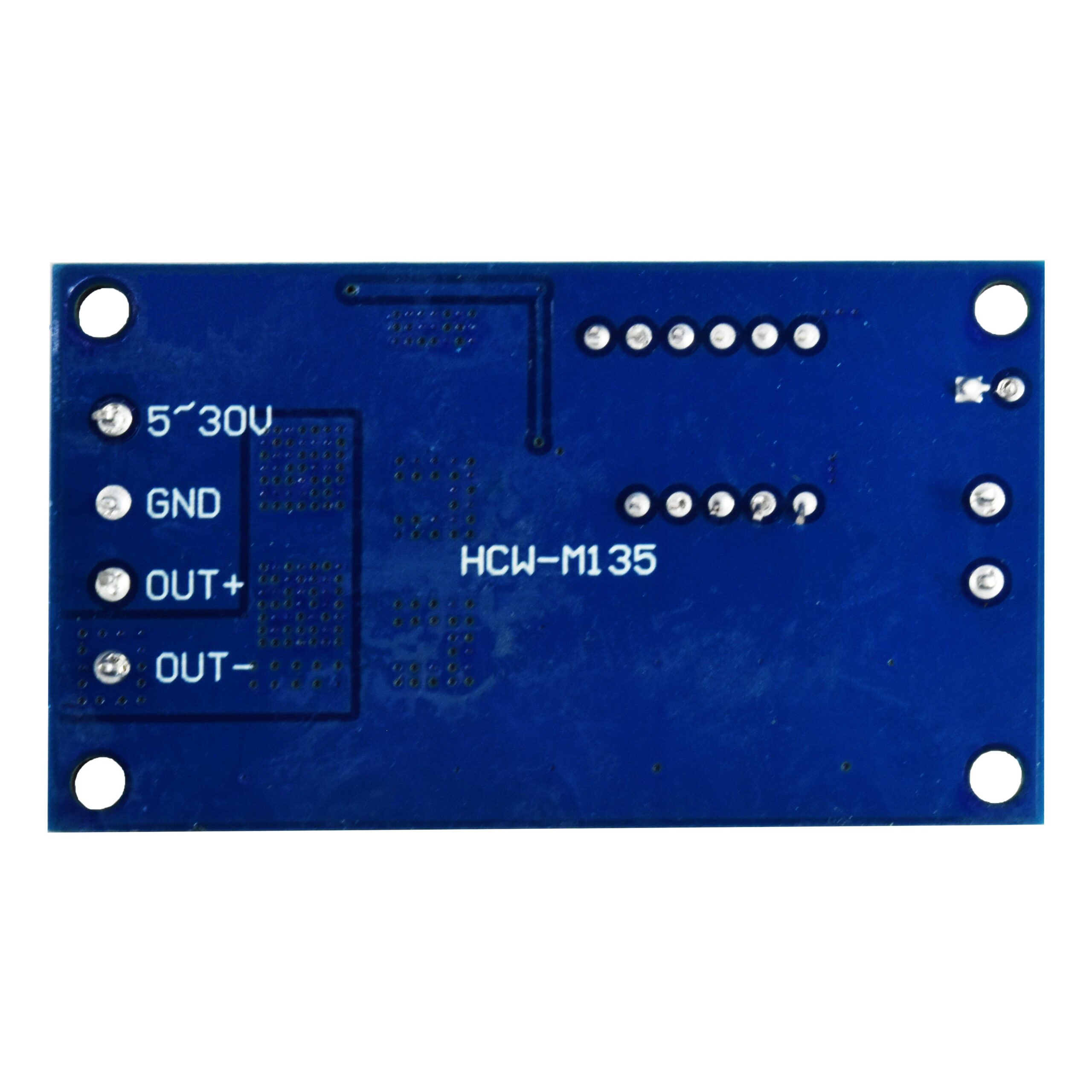
ماژول تایمر قابل تنظیم 12 تا 24 ولت با خروجی CMOS با جریان 20mA و اندازه 60×34.5x12mm و محدوده اندازه گیزی زمان 0.1 ثانیه تا 999 دقیقه قابل استفاده در انواع مدارات و پروژه های الکتریکی و الکترونیکی می باشد.
گارانتی اصالت و سلامت فیزیکی کالا
قیمت کالا:
ناموجود (ارسال فوری)
در انبار موجود نمی باشد
آخرین بروزرسانی قیمت: 19 تیر 1404
ماژول تایمر قابل تنظیم 12 تا 24 ولت با خروجی CMOS با جریان 20mA و اندازه 60×34.5x12mm و محدوده اندازه گیزی زمان 0.1 ثانیه تا 999 دقیقه قابل استفاده در انواع مدارات و پروژه های الکتریکی و الکترونیکی می باشد.تأمین و واردات قطعات هایتک را به ما بسپارید.
مشخصات ماژول تایمر قابل تنظیم 12 تا 24 ولت با خروجی CMOS
- منبع سیگنال تحریک High برابر است با 3 تا 24 ولت DC
- جریان 50mA
- جریان (idle) 20mA
- محدوده دمایی 40- تا 85
- اندازه 60×34.5x12mm
- محدوده اندازه گیزی زمان 0.1 ثانیه تا 999 دقیقه
- خروجی با توان 400W (5 تا 36 ولت DC با جریان دهی 15A در شرایط دمای اتاق)
- دارای ایزولاسیون سیگنال توسط اپتوکوپلر برای جلوگیری از نویز
- حفاظت در مقابل اتصال کوتاه و پلاریته معکوس
نحوه استفاده
- OP زمان وصل بودن رله
- CL زمان قطع بودن رله
- LOP تعداد تکرار عملیات
مدهای کاری
P1.1 با اعمال سیگنال تحریک رله به مدت OP ثانیه وصل می ماند و سپس قطع می شود. اعمال سیگنال تحریک مجدد اعتباری ندارد و تغییری ایجاد نمی کند.
P1.2 با اعمال هر سیگنال تحریک تایمر ریست می شود.
P1.3 با اعمال هر تریگر رله قطع و تایمر متوقف و ریست می شود
P2 با اعمال سیگنال تحریک به مدت زمان CL رله قطع بوده و سپس به اندازه OP وصل می شود و بعد از اتمام زمان OP رله قطع می شود.
P3.1 با اعمال سیگنال تحریک رله به مدت OP وصل شده و سپس به مدت CL قطع می شود و این عملیات به صورت حلقه ای تکرار می شود که تعداد تکرار بوسیله پارامتر LOP قابل تنظیم می باشد.
P3.2 با روشن شدن سیستم بدون نیاز به سیگنال تحریک مراحل فوق انجام می گیرد.
P4 تایمر با سیگنال تحریک شروع به کار کرده و رله وصل می شود و تا زمانی که سیگنال تحریک اعمال شود تایمر زمان OP ریست می شود. در صورتی که تا زمان پایان OP سیگنال تحریکی اعمال نشود رله قطع و برای وصل منتظر سیگنال تحریک می ماند.
-مدهای ذخیره انرژی
C-P بعد از پنج دقیقه بلا استفاده بودن سیستم، نمایشگر تایمر خاموش شده و سیستم یه مار عادی خود ادامه می دهد.
O-d با انتخاب این گزینه نمایشگر سیستم به حالت همیشه روشن به کار خود ادامه می دهد.
برای انتخاب بین دو حالت فوق کلید Stop را به مدت 2 ثانیه فشار می دهیم.
رنج زمانی تایمر
- XXX 1 تا 999 ثانیه
- XX.X 0.1 تا 99.9 ثانیه
- X.X.X 1 تا 99 دقیقه
برای مثال برای مقداردهی زمان 3.2 ثانیه باید به صورت “03.2” و یا برای 2 دقیقه با “0.0.2.” مقداردهی کرد.
-عملکرد Stop
وظیفه اصلی کلید توقف کلی سیستم به صورت اضطراری می باشد که دارای دو حالت می باشد
ON حالت وصل شدن رله برای انجام تنظیمات لحاظ شده
OFF رله قطع شده و به سیگنال تحریک پاسخی نمی دهد
تنظیمات پارامترهای مورد نیاز پس از قطع منبع انرژی محفوظ مانده و نیازی به برنامه ریزی مجدد نیست
به علت استفاده از تکنولوژی MOS سیستم طول عمر بالای دارد و تلفات در کمترین حد می باشد همچنین قدرت سوییچنگ بالایی در خروجی ارائه می دهد.
تنظیمات پارامترهای تایمر
برای تنظیم پارامترهای سیستم اعم از مد کاری و مدت زمان OP,CL ومقدار LOP کلید SET را به مدت 3 ثانیه فشار داده تا مدهای کاری نشان داده شود با استفاده از کلیدهای UP و DOWN یک مد کاری را انتخاب می کنیم برای تعیین پارامتر بعدی نیز SET را به صورت لحظه ای فشار داده و به همان ترتیب مقداردهی می کنیم و اگر در مد مورد نظر CL ویا LOP مورد نیاز باشد نیز به همین ترتیب عمل می کنیم در نهایت بعد از تنظیمات لازم دکمه SET را به مدت 3 ثانیه فشار می دهیم تا تنظیمات مورد نظر پیکربندی شود.
برای اطلاع از مقدار پارامترهای سیستم یا مد تنظیم شده با فشار دادن لحظه ای کلید SET همه پارامترها به صورت پشت سر هم نمایش داده می شوند.
برای ایجاد سیگنال تحریک پایه مثبت سیگنال تحریک به منبعی در محدوده ولتاژ DC به اندازه 3 تا 24 ولت متصل شده و کافی است دو زمین مدار را به هم اتصال دهیم تا سیگنال تحریک ایجاد شود.
برای راحتی این مورد نیز در سمت چپ برد محلی برای اتصال دو زمین قرار داده شده که با گذاشتن یک سوییچ با هر بار زده کلید شدن یک سیگنال تحریک ایجاد می شود. ایجاد تریگر سطح بالا با استفاده از مشترک کردن زمین های ورودی و سیگنال تحریک باعث ایجاد خاصیت ضد نویز نیز می شود.
Introduction
To achieve fast high frequency turn-on and off circuit, an unlimited number of switching times. No noise was made during turning on/off, no spark, and no electromagnetic interference.
Compared to normal electromagnetic relay modules, it has a longer service life. Dual-MOS in parallel active output, lower inner resistance, larger current, strong power;
at room temperature, operating current is up to 15A, power up to 400W, that can be used for most equipment. Wide voltage input from 5V to 36V, normally used for controlling DC motors, lights, LED strips, micro-pumps,
solenoid valves, etc., very convenient. It has an emergency stop function (“STOP” button) and reverse input protection. Automatically enter sleep mode and shut off display if no operation in 5 minutes,
and will be wake up by pressing any button. You can set different OP, CL, LOP parameters, which are independent of each other, and are saved separately. All parameter settings will be saved automatically if there is a power failure.
Specification
- Voltage: DC 5V~36V
- Trigger Signal Source: High voltage level trigger (3.0V~24V), signal ground and system ground are not on common ground to improve the system’s anti-jamming capability (you can also connect them on common ground).
- Output Capacity: DC 5V~36V, at room temperature, continuous current is 15A, power 400W. With enhanced heat dissipation, the current can be up to 30A
- Quiescent Current: 20mA
- Operating Current: 50mA
- Working Temperature: -40℃~85℃
- Clocking (Time Delay) Range: 0.1seconds to 999minutes
- Size: 60*34*12mm / 2.36*1.33*0.47″
Operating Mode
- P1: trigger signal, the relay is on “OP” time, and then disconnect; in the “OP” time, as follows:
- P1.1: signal is triggered again, invalid
- P1.2: signal is triggered interface again, the clocking is reset
- P1.3: Signal is trigger again reset, relay off, and stop the clocking;
- P-2: trigger signal, the relay off “CL” of time, interface the relay on “OP” time, and then disconnect relay after clocking;
- P3.1: trigger signal, the relay is turned on after the “OP” time, the relay off “CL” time, then the operation cycles; if trigger signal again during the cycle, the relay off, stop clocking; the number of cycles times ( “LOP “) can be set.
- P3.2: without triggering signal after power on, the relay is on “OP” time, the relay off “CL” time, then the operation cycles; the number of cycles times ( “LOP “) can be set.
- P-4: signal holding function. If there is trigger signal, clocking is reset, the relay remains on; when the signal disappears, after clocking “OP” time, the relay is off; if another signal is triggered during clocking, clocking will be reset.
How to Set Clocking Range :
After setting the parameter value at mode selection, press “STOP” button to set the clocking range;
XXX. The last decimal point lights up, range: 1 second to 999 seconds.
XX. X The second last decimal point lights up, range: 0.1 seconds to 99.9 seconds
X. X. X. all 3 decimal points light up, range: 1 minute to 999 minutes.
For example, if you want to set “OP” as 3.2 seconds, light up the second last decimal point, and set digit display as 03.2
Parameter Description: “OP” – on time, “CL” – off time, “LOP” – number of cycle times (1-999 times, “—” represents infinite loop).
These parameters are independent of each other, but are shared by each mode. For example, in P1.1 mode, set the on-time “OP” is 5 seconds, if you switch to P1.2 mode, its “OP” will also be 5 seconds.
In the main interface (display 000), press “SET” button will display “OP” ( “CL”, “LOP”) and the corresponding time XXX;
If the mode (such as the mode P1.1, P1.2, P1.3) only has “OP” time, press the “SET” key to display only the “OP” and the corresponding time;
Some models (such as the mode P3.1, P3.2) have parameters “OP”, “CL”, “LOP”, press “SET” button will display “OP” and the corresponding time, “CL” and the corresponding time, “LOP” and the corresponding number of times;
After setting mode, in the main interface press “SET” key to see information about the parameters of the current mode, very convenient.
How to Set Parameters
1. First, read the instructions to determine the required operating mode.
2. The module is powered up, the display at the current work mode (P1.1 default mode), then enter the main interface; press and hold “SET” button for 2 seconds to enter mode selection interface; then press “UP”, “DOWN” button to select the mode (P1.1 ~ P-4).
3. Select the mode (such as P3.2), then press the “SET” button, the parameter to be set flashes ( “OP” on-time, “CL” off time, “LOP” cycles ( “—” represents infinite loop)), press(or press and hold) “UP”, “DOWN” button to adjust the parameter value; then press the “STOP” key to set the decimal point position to select the clocking range (0.1 seconds to 999 minutes); press the “SET” button to set the next parameters of the current mode, method is same as above.
4. After the parameters are set, press and hold “SET” button for 2 seconds, then the current mode will flash once, and then return to the main interface, which means the parameters are successfully set.
The main interface: If the relay is not in work state, it display “000” with no decimal point), if it is in work state, it has decimal point.
Mode selection screen: Press and hold the “SET” button to enter; after setting, press and hold the “SET” button to exit back to the main interface.
Relays Enable Mode
1. ON: Relay allows conduction in the “OP” on-time;
2. OFF: Relay prohibits conduction and is always closed;
In the main interface, press the “STOP” button to switch between ON and OFF, the current state will flash, and then return to the main interface. (This feature is an emergency stop function, press on button to disconnect relay)
Sleep Mode
1. “C-P” Sleep mode: five minutes without any operation, the digital display automatically turns off, the program running as usual.
2. “O-d” Normal mode: digital display turns on always.
Press hand hold the “STOP” button for two seconds to switch “C-P” and “O-d” state, interface the current state flashes and then return to the main interface.
Note
1. The module is an active output, the output voltage equal to the input voltage.
2.’DC + ‘and’ load + ‘ are internally shorted(connected), but’ DC- ‘and’ load – ‘ cannot be shorted, otherwise the load cannot be controlled on and off, which is equivalent to load being powered on always.
Package Includes:
1 x Timer Switch Module
| وزن | 16.83 گرم |
|---|
سنسور سطح مایع غیر تماسی Y25
ماژول وای فای ESP8266-12E
ماژول گیرنده RXB61 315MHZ
ماژول گیرنده RXB61 433MHZ
ماژول GSM/GPRS/Bluetooth SIM800C اورجینال رجیستر شده
برای اطلاع از آخرین تخفیفها و جدیدترین کالاها در خبرنامه ثبتنام کنید.
- قطعات الکترونیک
- ماژولها و سنسورها
- سنسور دما
- سنسور نور و IR
- سنسور سطح مایع
- سنسور گاز
- ماژولهای GSM-GPS-GPRS
- گیرنده و فرستنده RF
- ماژول رله
- ماژولهای دما و رطوبت
- ماژولهای RF
- ماژولهای بلوتوث و WIFI
- ماژولهای تغذیه
- ماژولهای شارژ باتری و پاور بانک
- ماژول ولتمتر و آمپرمتر
- ماژولهای صوتی
- ماژولهای نمایشگر
- خرید ماژول و تگ RFID
- ماژولهای اثر انگشت
- ماژولهای التراسونیک
- کوره القایی ZVS
- ماژولهای مبدل-واسط
- ماژول پردازش تصویر و دوربین
- ماژولهای نوری و PIR
- ماژول LED و سگمنت
- دیمرهای AC و DC
- ماژول تایمر و پالس
- ماژولهای حرکت و لرزش
- ماژول درایور موتور
- ماژولهای کاربردی
- ال سی دی و نمایشگر
- کلید ، سوئیچ ، کیپد
- سوکت،کانکتور،فیش
- سیم و کابل
- انوع فیوز و جافیوزی
- پروگرامر و بردهای آموزشی
- ابزار آلات و تجهیزات اندازه گیری
- قطعات تعمیرات صنعتی
- قطعات خودرویی
- تجهیزات هوشمند سازی
- باتری،جاباتری،شارژر و آداپتور
- تجهیزات پزشکی
- قطعات مکانیک و رباتیک
- قطعات هیدرولیک و پنوماتیک
- دزدگیر و ردیاب
- محصولات حراجی آمازون


